SF INSPECT
Automated Collection of Characteristics
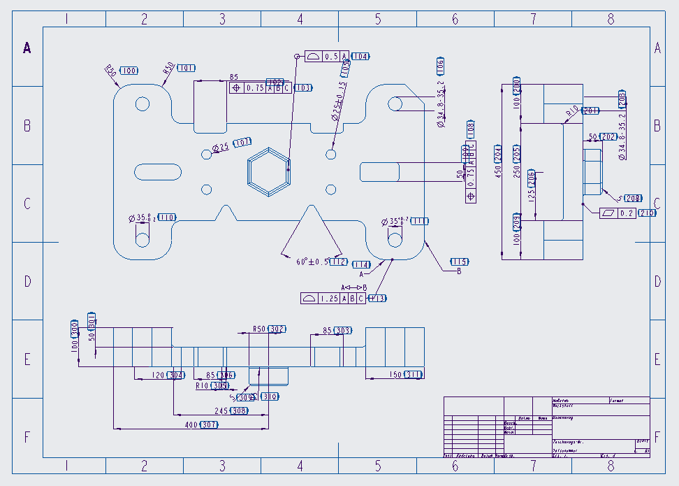
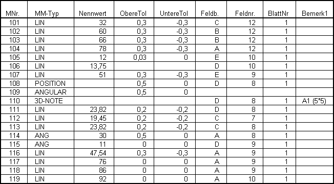
INSPECT for Creo is the system for automatically collecting, managing and documenting characteristics for Creo. At the push of a button, all characteristics are full-automatically determined from the CAD data, documented across the complete life cycle with a unique number, and labeled in the drawing. From that moment, all changes made to the 3D model and the drawing can be clearly traced and updated. The characteristic information, i.e. nominal values, tolerances, and links to the geometric information are provided in the Q-DAS Ascii transfer format (quasi standard in metrology), 3D geometric data is provided in Step AP 214. This enables an integrated process from design through to metrology, and highly automates geometric inspection based on the 3D model definition.
Current practice does not take advantage of the possibilities and potentials of an integrated and CAD based process. Often, practice is characterized by manual, time consuming, redundant tasks, and a manifold of interfaces.
With finished design and release of the part, the technical drawing of the part is used to create the inspection drawing. The characteristics to be inspected are determined based on 2D drawing information and labelled in the drawing with a unique characteristic number. This is partially performed by software – and more often on paper plots. The characteristics labelled that way are filled into forms, first article inspection (FAI) reports or CAQ systems by hand, forming a base for further quality processes in connection with the labelled drawing.
Every design change requires this process from scratch again – with additional effort for reusing the original characteristic numbers. New, deleted and modified characteristics need to be determined and entered into the CAQ system or forms. All in all, this poses a significant potential for errors like typos, read errors, comparison errors, outdated documents, and so on!
The solution to these problems is the consistent use of geometric characteristics, which have already been defined by design in the CAD system. All characteristics are directly deduced from the 3D model with IST geometry and dimensioning, and the drawing information. Hence, a process capable and consistent preparation and use of design data for inspection is secured with referential integrity of data („single source of truth“).
INSPECT determines the following information directly and automatically from the design data:
- Inspection dimensions with tolerances
- GD&T information with references
- Symbols (e.g. surface finishes, etc.)
- Notes
- References of dimensions and tolerances towards reference planes and axes
Characteristics are stored and managed directly in the CAD data. This guarantees a simple integration to PLM systems, as no additional functions and links are required by additional documents.
Based on a simple part with about 80 characteristics (inspection dimensions and tolerances), the magnitude of savings will be highlighted:
- Manual labelling and numbering of 80 characteristics: ca. 1 hour
- Creation of list of characteristics for these characteristics with number, type, nominal value, and tolerances with final verification: ca. 2-3 hours
- All in all, a qualified employee’s manual effort for ca. 3-4 hours
- With the CAD based approach and INSPECT these characteristics are prepared automatically and guaranteed error free within minutes
Through this automation, up to date characteristics can be supplied to downstream processes early and with minimal effort already during design or design changes. By managing change history, modified, new, and no longer existing characteristics are differentiated from current ones, and efforts to update downstream processes are minimized.
Q-DAS/CMM Extension
CAQ systems and offline programming systems for inspecting geometric quality often come with interfaces to 3D neutral files like Step, Iges … for directly accepting geometric information. These data only provide nominal values in implicit form via the geometric features, however. That means that the nominal value of an inspection dimension can only be concluded from the geometry, the information about upper and lower tolerance is completely missing. The Q-DAS/CMM Extension of INSPECT closes this gap in functionality and information. For every characteristic, the characteristic list in Q-DAS/CMM Ascii format (DFD) is expanded for the corresponding geometric elements like surfaces, axes, reference planes, and reference axes. This creates a significant potential to automate inspection and for choosing unified inspection strategies. This consistency offers further saving potential during creation of measuring programs. For the 80 characteristics mentioned before, manual creation of a measuring program is estimated at 1 day. With automated inspection planning this time is reduced to 1-2 hours.
Supported hardware and software:
INSPECT for Creo is available for the current and supported versions of PTC Creo, PTC Creo Elements/Pro and Pro/ENGINEER.
Release Notes for SF Inspect 2D (Version 7.2.2)
Download the Release Notes for SF Inspect 2D here.
Contact
Would you like to receive even more information about SF INSPECT? Our experts will be happy to answer your questions!


